Home
› Electrical Schematic Diagram Symbols : Wiring Diagram Symbol Meanings C230 Engine Fuse Box Wiring Wiring Yenpancane Jeanjaures37 Fr - Circuit symbols overview resistors capacitors inductors, coils, chokes & transformers diodes distinct symbols have been used to depict the different types of electronic components in circuits, since the very beginning of electrical and electronic science.
Electrical Schematic Diagram Symbols : Wiring Diagram Symbol Meanings C230 Engine Fuse Box Wiring Wiring Yenpancane Jeanjaures37 Fr - Circuit symbols overview resistors capacitors inductors, coils, chokes & transformers diodes distinct symbols have been used to depict the different types of electronic components in circuits, since the very beginning of electrical and electronic science.
Electrical Schematic Diagram Symbols : Wiring Diagram Symbol Meanings C230 Engine Fuse Box Wiring Wiring Yenpancane Jeanjaures37 Fr - Circuit symbols overview resistors capacitors inductors, coils, chokes & transformers diodes distinct symbols have been used to depict the different types of electronic components in circuits, since the very beginning of electrical and electronic science.. They are also known as circuit symbols or schematic symbols as they are used in electrical schematics and diagrams. An electronic symbol is a pictogram used to represent various electrical and electronic devices or functions, such as wires, batteries, resistors, and transistors, in a schematic diagram of an electrical or electronic circuit. This symbol represents an electrical conductor such as cables, wires etc. A schematic diagram is a picture that represents the components of a process, device, or other object using abstract, often standardized symbols and lines. All circuit symbols are in standard format and can be used for drawing schematic circuit they are mostly used to draw a circuit diagram and are standardized internationally by the ieee standard (ieee std 315) and the british standard (bs 3939).
Schematic diagrams describe the main and auxiliary circuits for control, signalling, monitoring and protection systems. A diagram that shows the connection of all components in a piece of equipment. This physics video tutorial explains how to read a schematic diagram by knowing what each electric symbol represent in a typical electrical circuit. These electrical schematic symbols will help you to identify parts when working with an electrical schematic. This symbol represents an electrical conductor such as cables, wires etc.
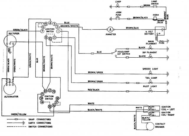
Electrical Symbols On Wiring Diagrams Meanings How To Read And What They Mean from www.weeksmotorcycle.com Importance of single line diagram. These electrical schematic symbols will help you to identify parts when working with an electrical schematic. The symbols represent electrical and electronic components. The diagram symbols in table 1 are used by square d and, where applicable, conform to nema (national electrical manufacturers association) wiring diagram. Ciircuits, diagrams & symbols includes: A schematic diagram is a picture that represents the components of a process, device, or other object using abstract, often standardized symbols and lines. > edraw symbol > electrical symbols for electrical schematic diagrams. The simple crossing on the left is correct but may be misread as a join where the 'blob' has been.
This physics video tutorial explains how to read a schematic diagram by knowing what each electric symbol represent in a typical electrical circuit.
To read and interpret electrical diagrams and schematics, the basic symbols and conventions used in the drawing must be understood. Schematic diagrams describe the main and auxiliary circuits for control, signalling, monitoring and protection systems. Although schematic diagrams are commonly associated with electrical circuits, many examples can be found in other industries. Complete circuit symbols of electronic components. Download high quality circuit schematic symbols images of common electrical and electronics components, for creating any schematic diagram. These electrical schematic symbols will help you to identify parts when working with an electrical schematic. An electrically operated switch that includes motor overload protection. An electrical symbol is a small image used to represent an electrical or electronic device or function. This version recognizes that electrical diagrams are a factor in international trade: This article shows many of the frequently used electrical symbols for drawing electrical. 01_b_r03 electrical basics drawing index. All circuit symbols are in standard format and can be used for drawing schematic circuit they are mostly used to draw a circuit diagram and are standardized internationally by the ieee standard (ieee std 315) and the british standard (bs 3939). This physics video tutorial explains how to read a schematic diagram by knowing what each electric symbol represent in a typical electrical circuit.
Electronics symbols for schematics and wiring diagrams are mostly universal with a few of the symbols that may look different if reading other types of schematics. Ciircuits, diagrams & symbols includes: When building a circuit, this electrical connection can be made. Electrical circuit schematic symbols are graphical sign, that is used to design electronic, electrical circuit schematic diagram. As you go through various parallax microcontroller tutorials, you will see schematics describing the circuits to be built.
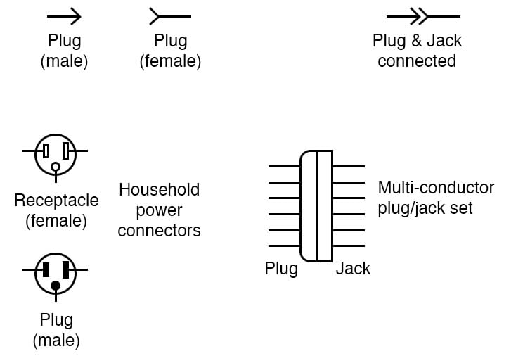
Connectors Circuit Schematic Symbols Electronics Textbook from www.allaboutcircuits.com This symbol represents an electrical conductor such as cables, wires etc. It can be used for a zero potential reference point from where current is measured. > edraw symbol > electrical symbols for electrical schematic diagrams. An electrically operated switch that includes motor overload protection. A schematic diagram is a picture that represents the components of a process, device, or other object using abstract, often standardized symbols and lines. Circuit symbols are used in circuit diagrams (schematics) to represent electronic components. Electronics symbols for schematics and wiring diagrams are mostly universal with a few of the symbols that may look different if reading other types of schematics. Electrical circuit schematic symbols are graphical sign, that is used to design electronic, electrical circuit schematic diagram.
A motor is an electrical machine that converts electrical energy into mechanical energy.
All circuit symbols are in standard format and can be used for drawing schematic circuit they are mostly used to draw a circuit diagram and are standardized internationally by the ieee standard (ieee std 315) and the british standard (bs 3939). An electrical symbol is a small image used to represent an electrical or electronic device or function. These electrical schematic symbols will help you to identify parts when working with an electrical schematic. A ground symbol (iec symbol 5017) identifies a ground terminal. Create electrical circuit diagrams and schematics with electrical symbols provided by smartdraw software. Download high quality circuit schematic symbols images of common electrical and electronics components, for creating any schematic diagram. Importance of single line diagram. Ciircuits, diagrams & symbols includes: This symbol represents an electrical conductor such as cables, wires etc. They are also known as circuit symbols or schematic symbols as they are used in electrical schematics and diagrams. It can be used for a zero potential reference point from where current is measured. This article shows many of the frequently used electrical symbols for drawing electrical. Schematic diagrams describe the main and auxiliary circuits for control, signalling, monitoring and protection systems.
They are also known as circuit symbols or schematic symbols as they are used in electrical schematics and diagrams. This article shows many of the frequently used electrical symbols for drawing electrical. An electrically operated switch that includes motor overload protection. When building a circuit, this electrical connection can be made. This is a generic symbol used for electrical motor in any electrical schematic designs.
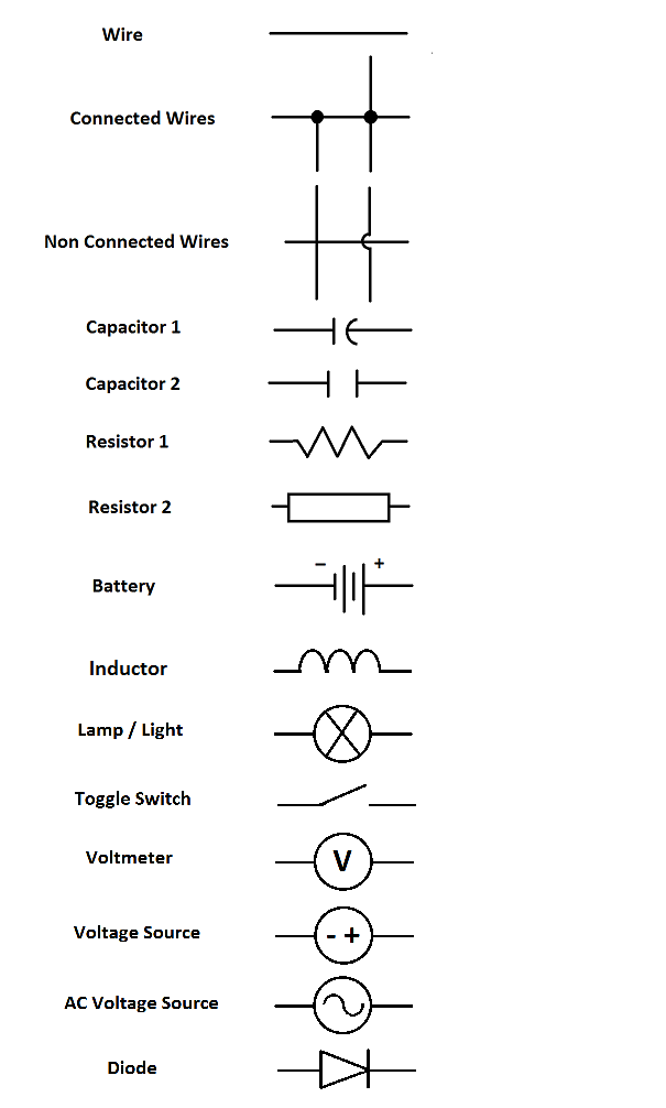
A Beginner S Guide To Circuit Diagrams Electrical Engineering Schools from www.electricalengineeringschools.org They are drawn in sufficient the characteristics of the 'black boxes' are identified by standard symbols and further reference to the complex circuitry inside the 'black boxes' may be. > edraw symbol > electrical symbols for electrical schematic diagrams. This physics video tutorial explains how to read a schematic diagram by knowing what each electric symbol represent in a typical electrical circuit. Single line or online electrical diagrams uses these schematic symbols to indicate the paths and components of an electrical circuit. The use of one common symbol language ensures a clear presentation and economical diagram preparation for a variety of users. It can be used for a zero potential reference point from where current is measured. Electrical & electronic symbols and images are used by engineers in circuit diagrams and schematics to show how a circuit layouts and schematic diagrams are a simple and effective way of showing pictorially the electrical connections, components and operation. All circuit symbols are in standard format and can be used for drawing schematic circuit they are mostly used to draw a circuit diagram and are standardized internationally by the ieee standard (ieee std 315) and the british standard (bs 3939).
Complete circuit symbols of electronic components.
As you go through various parallax microcontroller tutorials, you will see schematics describing the circuits to be built. Piping and instrumentation symbols dialog box, click equipment. Electrical symbols and electronic circuit symbols are used for drawing schematic diagram. All circuit symbols are in standard format and can be used for drawing schematic circuit they are mostly used to draw a circuit diagram and are standardized internationally by the ieee standard (ieee std 315) and the british standard (bs 3939). This symbol represents an electrical conductor such as cables, wires etc. When building a circuit, this electrical connection can be made. To read and interpret electrical diagrams and schematics, the basic symbols and conventions used in the drawing must be understood. A motor is an electrical machine that converts electrical energy into mechanical energy. Single line or online electrical diagrams uses these schematic symbols to indicate the paths and components of an electrical circuit. Create electrical circuit diagrams and schematics with electrical symbols provided by smartdraw software. There is a quite adequate collection of symbol for electrical, electronic circuit. This is a generic symbol used for electrical motor in any electrical schematic designs. Circuit symbols overview resistors capacitors inductors, coils, chokes & transformers diodes distinct symbols have been used to depict the different types of electronic components in circuits, since the very beginning of electrical and electronic science.