Home
› Heat Pump System Diagram - Troubleshooting Challenge A Split System Heat Pump That S Not Cooling 2013 11 04 Achrnews - Multiple power sources may be present.
Heat Pump System Diagram - Troubleshooting Challenge A Split System Heat Pump That S Not Cooling 2013 11 04 Achrnews - Multiple power sources may be present.
Heat Pump System Diagram - Troubleshooting Challenge A Split System Heat Pump That S Not Cooling 2013 11 04 Achrnews - Multiple power sources may be present.. In addition to the evaporator and condenser, the heat pump system also has a compressor and a metering device. Important components of a heat pump system. Some heat pumps contain a scroll. The diagram below shows a heat pump piping layout. Free quotes from heat pump contractors near you.
A water source heat pump extracts heat from the water when in the heating mode and rejects heat to the water when in the cooling mode. The system's switch point from the heat pump to the gas furnace can be set on the thermostat or control system by you or your dealer. Your heat may be different than the one described here. Goodman heat pump wiring schematic. The sequence for defrost mode is timed for defrost mode.
Cv 8103 With Water Source Heat Pump System Diagram On General Pump Diagram Schematic Wiring from static-cdn.imageservice.cloud Common device types include air source heat pumps, ground source heat pumps, water source heat pumps and exhaust. Save money by comparing costs. Always refer to your instructions when wiring up a system to ensure you are wiring to the manufactur. The heat pump wiring diagram above covers approximately 90% of the heat pump thermostats. Free quotes from heat pump contractors near you. Your heat may be different than the one described here. The color of wire r is usually red and c is black. An improperly designed ductwork systems can cost money through inefficiencies, and in some cases, cause premature failure of heating and cooling equipment.
Goodman heat pump wiring schematic.
When the defrost mode initiates, the defrost control shifts the reversing valve to the air conditioning mode. Always refer to your instructions when wiring up a system to ensure you are wiring to the manufactur. This is a brief overview of heat pump thermostat wiring. Heat pump thermostat wiring chart diagram. Common device types include air source heat pumps, ground source heat pumps, water source heat pumps and exhaust. All heat pumps use a vapor compression cycle to transport heat from one location to another. These two system components maintain the flow of refrigerant through the heat pump system and also maintain the heat transfer coils at the desired temperatures and pressures. For diy system we recommend horizontal ground loops as the easiest method of installation. Then, by heating/cooling that air, delivering the newly conditioned air to your home. Learn from the experts at standard heating about hvac installation! A heat pump is a device used to warm and sometimes also cool buildings by transferring thermal energy from a cooler space to a warmer space using the refrigeration cycle, being the opposite direction in which heat transfer would take place without the application of external power. Some heat pumps contain a scroll. Disconnect all power before servicing or installing this unit.
1) condenser, 2) expansion valve, 3) evaporator, 4) compressor. All heat pumps use a vapor compression cycle to transport heat from one location to another. Heat pump thermostat wiring chart diagram. Click back and forth between buttons 2 and 3 and note how the discharge from the compressor is diverted to different coils in each mode. From one medium to another.
Everything You Need To Know About Hvac Systems from twentyonecelsius.com.au Standard heat pump system, auxiliary heater requires pump of heat pump, monoenergy (dhw by heat pump and auxiliary heater or simple hybrid system (dhw by boiler only) (system diagram = 8, no vr 70) 6. A heat pump system has four major system components. Heat engines, heat pumps, refrigerators, and air conditioners are examples of such systems. The system's switch point from the heat pump to the gas furnace can be set on the thermostat or control system by you or your dealer. Save money by comparing costs. In canada and northern usa we supply 800 feet coils per loop. The sequence for defrost mode is timed for defrost mode. A heat pump is a device used to warm and sometimes also cool buildings by transferring thermal energy from a cooler space to a warmer space using the refrigeration cycle, being the opposite direction in which heat transfer would take place without the application of external power.
A heat pump system has four major system components.
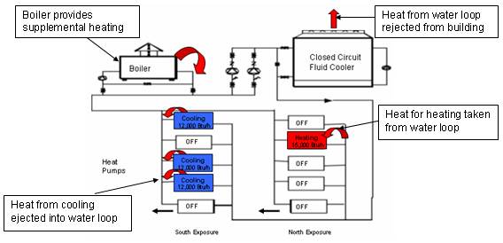
Our hvac diagram helps you understand the different components of your residential heating and cooling system. From one medium to another. You can also view the 2 modes showing the refrigerant states with buttons 4 and 5. These two system components maintain the flow of refrigerant through the heat pump system and also maintain the heat transfer coils at the desired temperatures and pressures. Each plays an important role in the troubleshooting process. Click back and forth between buttons 2 and 3 and note how the discharge from the compressor is diverted to different coils in each mode. Your heat may be different than the one described here. Standard heat pump system, auxiliary heater requires pump of heat pump, monoenergy (dhw by heat pump and auxiliary heater or simple hybrid system (dhw by boiler only) (system diagram = 8, no vr 70) 6. The heat pump works in conjunction with the air handler to distribute the warm or cool air to interior spaces. For diy system we recommend horizontal ground loops as the easiest method of installation. The sequence for defrost mode is timed for defrost mode. In canada and northern usa we supply 800 feet coils per loop. Heat is moved through an interconnected water loop and either rejected through a cooling tower, or put to work in other areas.
Heat engines, heat pumps, refrigerators, and air conditioners are examples of such systems. Your heat may be different than the one described here. The color of wire r is usually red and c is black. The heat pump wiring diagram above covers approximately 90% of the heat pump thermostats. In addition to the electrical components and a fan, a heat pump system includes:
Hvac Aplication Water Source Heat Pump Systems from www.iklimnet.com Always refer to your instructions when wiring up a system to ensure you are wiring to the manufactur. In canada and northern usa we supply 800 feet coils per loop. Identify the system of interest and draw a labeled diagram of the system showing energy flow. Your heat may be different than the one described here. A wiring diagram is a simplified standard photographic depiction of an electrical circuit. Heat engines, heat pumps, refrigerators, and air conditioners are examples of such systems. A heat pump system has four major system components. Heat is moved through an interconnected water loop and either rejected through a cooling tower, or put to work in other areas.
All heat pumps use a vapor compression cycle to transport heat from one location to another.
System composite diagram heat pumps 10 kw & below #18 ga. Standard heat pump system, auxiliary heater requires pump of heat pump, monoenergy (dhw by heat pump and auxiliary heater or simple hybrid system (dhw by boiler only) (system diagram = 8, no vr 70) 6. For diy system we recommend horizontal ground loops as the easiest method of installation. Multiple power sources may be present. From one medium to another. Each plays an important role in the troubleshooting process. Heat is moved through an interconnected water loop and either rejected through a cooling tower, or put to work in other areas. You can also view the 2 modes showing the refrigerant states with buttons 4 and 5. When the defrost mode initiates, the defrost control shifts the reversing valve to the air conditioning mode. Our hvac diagram helps you understand the different components of your residential heating and cooling system. The heat pump wiring diagram above covers approximately 90% of the heat pump thermostats. In canada and northern usa we supply 800 feet coils per loop. Variety of goodman heat pump wiring schematic.